


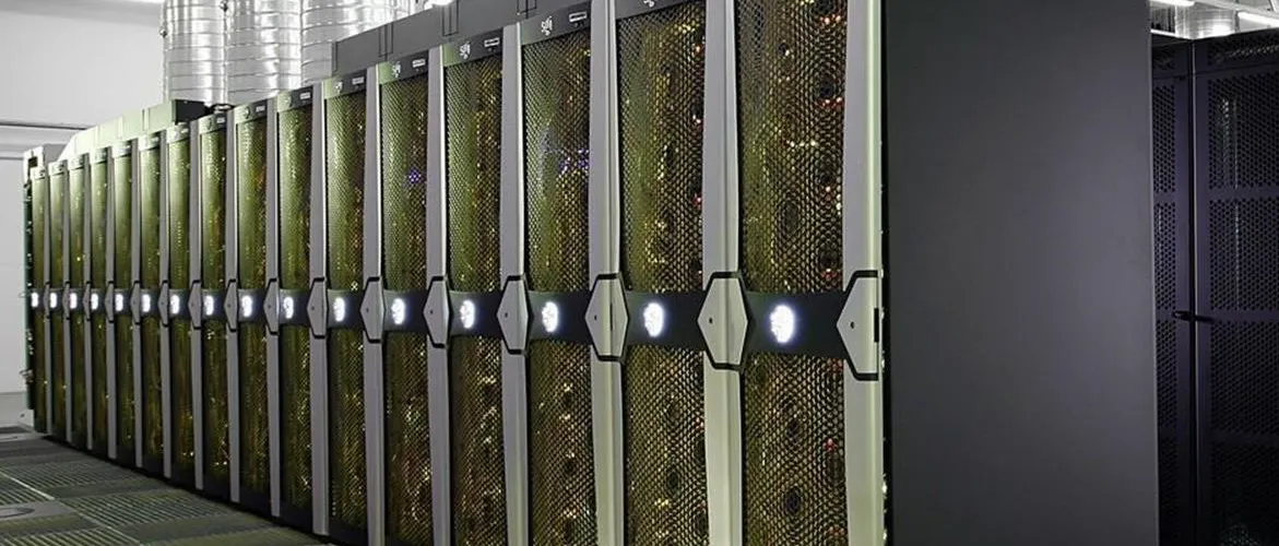
Conventional build
Design, procurement and construction executed on site with all trades sequenced under one programme. The right route where the building exists, the space is available, and works can be phased around live operations.
Data Centers — A Convergent Technology Business Unit
From whitespace planning to commissioning to managed services — Convergent's Data Center Business Unit builds the facilities Saudi enterprise and government operations depend on.
PREVIEW MEDIA — REPLACEMENT REQUIRED. Controlled preview asset from the CT design pack. Not a photograph of a Convergent premises or project.
Detailed capabilities, technical information and enquiry routes for this discipline are published on its own website.
From the incoming supply to the cabinet, a facility is one path — and every link in it is a place the room can stop. This is the chain the design is arranged around, drawn as a single line.
Incoming supply, protection and metering
Stepped down to the distribution the building runs at
Protection, isolation and the changeover point
The path that carries the load when the utility does not
Rectifier, store and inverter — with a bypass around them
Distribution and metering down to the cabinet
Heat rejection is on the same essential supply — a hall that loses cooling stops shortly after one that loses power.
Metering and monitoring sit on every stage, because a chain is only maintainable if its state is known.
A data center is not a room with servers in it. It is a set of interdependent engineered systems — power, cooling, containment, detection, access — that have to hold together continuously, under load, for the life of the asset.
The applications a business runs on are the visible layer. Underneath them sits a facility whose only job is to remove the reasons they might stop: a utility failure, a thermal excursion, water, fire, an unauthorised entry, a maintenance activity nobody designed to be survivable. Each of those is a separate engineering discipline, and each one fails on its own terms.
That is why facility work rewards single accountability. When power, cooling, containment, cabling, detection and access are contracted separately, the space between them belongs to nobody — and that space is where availability is actually lost. This Business Unit is organised around holding all of it under one design intent and one commissioning programme.
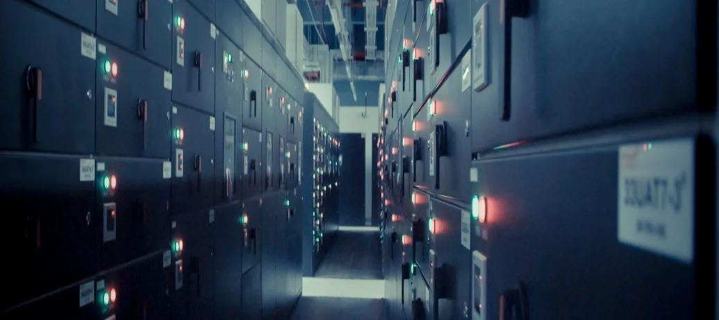
The redundancy level is an input to the design. It decides topology, plant selection, and whether the facility can be maintained without being taken down. It cannot be fitted afterwards to a building that was not laid out for it.
Availability is usually lost at the boundary between two scopes rather than inside either one. A single design intent and a written interface register is how that boundary stops being nobody’s job.
The equipment in the racks is replaced several times over the life of the plant and distribution around it. Facility decisions are the long ones, and they are the expensive ones to revisit.
A facility is delivered as seven engineered systems that have to agree with one another — about load, about clearance, about failure behaviour, and about who is holding what. They are engineered together, from the slab up.
The room itself: raised access floor to the required load class, pedestal layout, cut-outs, sealing and grounding, set out against the distribution and containment that will run beneath it.
Utility intake, switchgear, uninterruptible power, standby generation and distribution down to rack level, arranged to the redundancy the facility is designed to hold, and metered where the operator needs to plan from.
Precision cooling plant sized to the design load, an airflow strategy the room can actually achieve, and control logic that holds temperature and humidity inside the envelope the equipment is warranted against.
Rack selection to the depth and load required, power distribution inside the cabinet, blanking and brush management, and hot- and cold-aisle containment that makes the cooling strategy real rather than theoretical.
Passive and active components: backbone and horizontal distribution, pathways and containment, patching fields, labelling schedules, and the test records the operator is handed at the end.
Early-warning detection appropriate to a technical space, suppression selected for a room people work in, leak detection beneath the floor, and the interlocks that tell the mechanical and electrical systems what to do about it.
Environmental and power monitoring, alarm thresholds and reporting set by the operator rather than by us, and defined interfaces to the wider building systems at an agreed protocol and point list.
Commissioning runs as a ladder. Nothing moves up a rung until the rung below it has been witnessed and signed. The last rung is the one that matters: the failure modes the redundancy exists for are induced deliberately, under load, and the facility’s response is recorded.
Plant is witnessed at the manufacturer against the specified performance before it ships, so a rejection costs a delivery slot rather than a site programme.
Delivery inspection, installation verification and pre-functional checklists per component, signed off before anything is energised.
Each system is proved to do what the design says it does, on its own, across the range it is expected to operate over.
Systems are proved to do it together. Utility loss, plant failure and changeover are induced under load, and the facility’s actual behaviour is measured against design intent.
As-builts, test records, settings registers, spares position and operator training, issued as the pack the facility is subsequently run from.

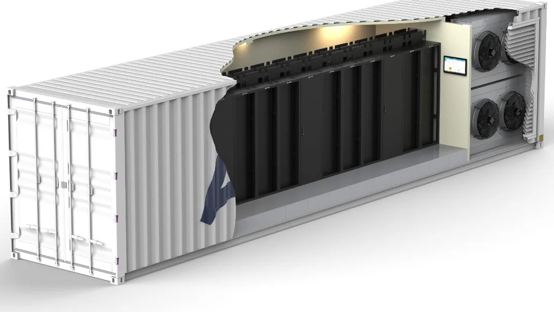
Where site conditions, programme or remoteness make conventional construction the wrong instrument, the same engineered scope is delivered prefabricated: built and tested complete in a controlled environment, then deployed. Testing comes off the critical path, and site time reduces to placement, interconnection and integrated testing.
Design, procurement and construction executed on site with all trades sequenced under one programme. The right route where the building exists, the space is available, and works can be phased around live operations.
The facility is engineered as modules, fabricated and factory-tested complete, then transported and deployed. The right route where the programme is short, the site is remote, or repeatable capacity is being rolled out.
A well-engineered facility does not stay available on its own. These are the tracks this Business Unit runs under a support agreement, scaled to the coverage the client contracts for.
Scheduled intervention on the plant availability depends on, against the regime set at handover and adjusted from what the equipment actually reports.
Trending on the parameters that precede a failure, so an intervention is planned into a maintenance window instead of taken as an incident.
Fault attendance and repair under the contracted response and coverage model, with root cause recorded against the asset rather than against the call.
Environmental and power monitoring with alarm notification against operator-set thresholds, reported back on an agreed cycle.
Training for the client’s own team on the systems as they were actually built, and the documentation set they need to run them without us.
Critical-spares position and procurement routes agreed against real lead times, so an outage is not extended by a supply chain.
Facility work always meets somebody else’s work. Each boundary below is registered, given a named owner on both sides, and closed with a deliverable rather than an assumption.
The facility’s passive infrastructure terminates at the patching field. Active network architecture, configuration and operation is the IT Infrastructure Business Unit’s scope, designed against the same drawings.
Cabling test records and port schedules
Facility monitoring presents to the wider building management system at an agreed protocol and point list, rather than being merged into it and losing its own alarm path.
Point list and interface specification
Room and rack access control is delivered inside the facility scope. Estate-wide security policy and platform ownership is agreed with the client’s own security function before configuration.
Access schedule and audit configuration
Where the base building belongs to another contractor, structural loading, fire compartmentation and services penetrations are registered and jointly signed rather than assumed.
Interface register with named owners
Tell us what you are planning, where the scope sits and the outcome that matters. Your enquiry is directed to the Business Unit that owns that field, and you deal with that team directly.
Most engagements are led by a single Business Unit working directly in its field. Where a requirement genuinely crosses disciplines, the Group coordinates the points where those specialist scopes meet, without diluting the expertise behind each one.
ISO 9001:2015, ISO/IEC 27001:2022, ISO 37001:2016 and ISO 45001:2018, within the certified scope of Data Centre Solutions and Services. The certified scope is stated on every page where the standards appear.
A consistent approach across every Business Unit, scaled to the requirement: understand the environment and constraints, engineer against the relevant standards, coordinate where specialist scopes meet, deliver and commission the agreed scope, then support it to the contracted model.
Company facts, capabilities and certified management systems are assembled for procurement officers and evaluation teams, with a controlled prequalification pack available on request through the Evaluation Center.
ISO 9001:2015, ISO/IEC 27001:2022, ISO 37001:2016 and ISO 45001:2018, within the certified scope of Data Centre Solutions and Services.
| Standard | Subject | Certified scope |
|---|---|---|
| ISO 9001:2015 | Quality management | Data Centre Solutions and Services |
| ISO/IEC 27001:2022 | Information security | Data Centre Solutions and Services |
| ISO 37001:2016 | Anti-bribery management | Data Centre Solutions and Services |
| ISO 45001:2018 | Occupational health and safety | Data Centre Solutions and Services |
Convergent's Data Center team works with procurement officers, CIOs, and engineering consultants from feasibility through commissioning. Tell us about your project.